


ColorHunter Technology is an innovative technology that provides vivid colors, appropriate brightness and clear images in low light.

Enter the 'Motion' menu from the device's menu, select the camera and select 'Alarm output'
| NEUTRONLIFE SMARTHOME UYGULAMASI | ||
| Özellik | Açıklama | Limit |
| Program Sayısı | Bir cihaz için oluşturulabilecek maksimum program sayısı | 30 |
| Ev Cihaz Sayısı | Bir eve eklenebilecek maksimum cihaz sayısı | 200 |
| Sahne Sayısı | Bir ev için oluşturulabilecek maksimum sahne sayısı | 100 |
| Otomasyon Sayısı | Bir ev için oluşturulabilecek maksimum otomasyon sayısı | 100 |
| Sahne Eylem Sayısı | Bir sahnede oluşturulabilecek maksimum eylem sayısı | 150 |
| Otomasyon Eylem Sayısı | Bir otomasyon sahnesinde oluşturulabilecek maksimum eylem sayısı | 150 |
| Otomasyon Koşul Sayısı | Bir otomasyon sahnesinde oluşturulabilecek maksimum koşul sayısı | 10 |
| Eş Zamanlı Oturum Açma Sayısı | Eş zamanlı oturum açma için tek bir hesap tarafından desteklenen maksimum mobil cihaz sayısı | 200 |
| Ev Sayısı | Bir hesabın oluşturabileceği maksimum ev sayısı | 20 |
| Ev Üyesi Sayısı | Bir eve eklenebilecek maksimum üye sayısı | 20 |
| Oda Sayısı | Bir ev için oluşturulabilecek maksimum oda sayısı | 20 |
| Oda Cihaz Sayısı | Bir odaya eklenebilecek maksimum cihaz sayıs | 50 |
| Cihaz Grubundaki Cihaz Sayısı | Bir cihaz grubuna eklenebilecek maksimum cihaz sayısı | 100 |
| Ev Cihazı Grup Sayısı | Bir ev için oluşturulabilecek maksimum cihaz grubu sayısı | 20 |
| Cihaz Grubu Paylaşımında Kullanıcı Sayısı | Tek bir cihaz grubunun paylaşılabileceği maksimum kullanıcı sayısı | 20 |
| Cihaz Paylaşımında Kullanıcı Sayısı | Tek bir cihazın paylaşılabileceği maksimum kullanıcı sayısı | 20 |
| Birleştirilen Ev Sayısı | Bir hesabın katılabileceği maksimum ev sayısı | 20 |
| DİĞER | ||
| Özellik | Açıklama | Limit |
| Ürün Sayısı | NeutronLife IoT Platformunda oluşturulabilecek maksimum ürün sayısı | 500 |
| MQTT Mesaj Uzunluğu | Bir MQTT mesajının maksimum boyutu. Bu boyutu aşan MQTT mesajları doğrudan atılacaktır. | 64 KB |
|
Tetik mekanizması: |
||
1. Access the 'password settings' menu by tapping the 'admin' icon at the top right.
2. In the window that opens, select 'Public user' to create a password for the user. Then mark the area it will control.
3. Follow the steps below to control other fields on the keypad:
- Enter the 'General settings' menu.
- Select the 'Other settings' menu.
- Enter the 'Keyboard area settings' menu.
- Select the keypad number you want to control from the 'Keypad number' menu.
- Select the fields you want to control from the 'Field' menu and save.
You can follow these steps to control different areas on the keypad:
- Enter the setup password.
- Tap the 'Area' icon.
- Select the area you want to control.
You can now install or unfreeze the area of your choice.
1. Access the user interface or control panel of the device where you are controlling the Speed Dome.
2. Enter the numbers 96-10-12-12 respectively. After each digit, you will need to press the "Start" or "Preset" key on the unit you are controlling.
When you do this, the AHD Speed Dome will automatically reset itself to the default settings. This will reset the Speed Dome's configuration and settings and return to its starting point.
1. Type your menu password to access the menu via the keypad.
2. Scroll through the menu and enter the 10th "Other Settings" menu.
3. In the "Other Settings" menu, type 2001 in the desired code menu.
4. After entering 2001, press the "Enter" key.
This action will restore the NTA-GNA8545 panel to its default settings. The panel will reset to its factory settings, resetting all previously configured settings and returning to the starting point.
*To activate, from the device's menu
-Enter the alarm menu
-Select alarm output
-Select as NO
You can specify SN from the menu.
1. To access the panel's web interface, open your browser and enter the panel's IP address.
2. Enter the general settings menu.
3. Enter the scene management menu.
4. Enter the PGM connection menu.
5. Click the "PGM connection" button from the menu that comes up.
6. Use the "Event Type" to select:
- Selecting "FIELD" activates PGM for all detectors in the area you selected.
- When "Zone" is selected, PGM is activated for up to 8 zones you have marked.
- When "System" is selected, PGM is activated when an alert type you specify is active.
7. Mark "PGM NO" as 1 because there is only 1 PGM output on the panel.
8. Set "PGM STATUS":
- Normally 0 voltage in "On" state, 12V in alarm state.
- Normally 12V in "Off" state, 0 voltage in alarm state.
9. Type the duration you want in the "Validity Period" section. This time specifies the recovery time after the alarm is triggered. Note: By default, the recovery time after triggering is 17 minutes.
Example: When 12V comes on after the alarm is triggered, if you set the time to "5" seconds, it will be 0 voltage again after 5 seconds.
1. Open your browser and enter the IP address to access the IP camera's user interface.
2. Enter the "Install" or "Setup" menu.
3. Enter the "Video" section.
4. Change the "Encoding Format" to "MJPEG" from the menu and save the change.
5. Then enter the "Security" menu.
6. Scroll to "NETWORK SECURITY".
7. In the "RTSP Authentication" tab, mark both options as "none".
8. Save your changes.
The feature called "Corridor Mode" requires that both the NVR (Network Video Recorder) device and the camera support this feature. Corridor Mode is used in widescreen monitors or special applications that require portrait orientation to make better use of a vertical space.
There are the following requirements for Corridor Mode to work:
1. NVR device: NVR device must support Corridor Mode feature.
2. Camera: The camera must also support the Corridor Mode feature. Models that support Corridor Mode have the option to display vertically (rotated 90° horizontally). This option allows the cameras to record the image vertically and display it properly on the NVR.
Remember, both the NVR and the cameras must be properly configured to enable and use Corridor Mode.
1. Type your menu password to access the menu via the keypad.
2. Scroll through the menu and enter the 10th "Other Settings" menu.
3. In the "Other Settings" menu, type 100 in the desired code menu.
4. After entering the number 100, you can see the reception strength of your current GSM signal on the screen.
Gravity is between 1 and 32 as standard.
In some STAR IP cameras, the feature called "HLC" is referred to as "Spot Metering" in some models. You can follow the steps below to set this feature:
1. Open your browser and enter the IP address of the camera to access the user interface.
2. Go to the "Setup" or "Setup" menu.
3. Select the "Image" option.
4. In the menu that opens, find "Image Exposure" or a similar option. Choose this option.
5. Go to the "Measurement Control" tab.
6. There should be an option here called "HLC" or "Spot Metering". Find and enable this option.
7. Select the relevant option to adjust the settings. This feature determines the focal point of the camera and adjusts the exposure values accordingly.
1. Call the panel by phone.
2. The answering machine will ask you to enter the 4-digit password you set and deactivate the alarm.
3. Enter the 4-digit password and then press the "#" key.
4. After performing this operation, you can control the panel.
Calling the panel by phone requires you to enter your 4-digit password via the answering machine. After entering the password, you can control the panel by pressing the "#" key.
IPC2322SB-HDZK-I0
IPC6612SR-X25-VG
IPC6424SR-X25-VF
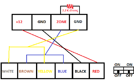
Combine Blue and Brown, Yellow and White.
1. Connect the "white" and "yellow" (yellow) leads of the detector.
2. Connect these joined leads together with a resistor to "GND" (ground) on the panel.
3. Connect the "brown" and "blue" leads of the detector.
4. Connect these joined leads together with a resistor to the "ZONE" on the panel.
5. Turn both switches on the detector to the "OFF" position.
With the NMANAGER program, you can view people counting data in a specific time period (day, week, month, year).
Please use 2.2K resistor when connecting with the panel.
1. Press and hold the * key for 3 seconds to add a card.
2. To enter the menu, enter the numbers 987699, then press the number 7 and then the # key.
3. To add the second card, press 0-2-# keys in order to bring the new card closer to the keypad.
4. Exit the menu by pressing the * key after hearing the warning sound.
1. Open the front cover of the smart key.
2. Press and hold the black keys below the buttons.
3. When the LEDs flash three times, release the black button.
4. Press one of the rightmost keys on the remote.
5. Repeat this process for each black button on the smart key.
- Press the black button again for the second black button and press the second rightmost button on the remote.
- Press the black button again for the third black button and press the third rightmost button on the remote.
When you follow these steps, your smart key and remote will be paired. The LEDs on the smart key will flash when the control keys are pressed, indicating that the operation is done correctly.
89 – 1 = Normal
89 – 2 = 12V with power off
89 – 3 = 12V when alarm is armed
89 – 4 = Normally 15V 5V with alarm activated
89 – 5 = Communication error
| Yellow | Green | Blue | Black | Red |
| NC | NO | COM | GND | +12V |
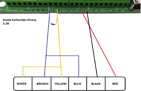
1. Connect the detector's "yellow" wire with a 2.2K resistor.
2. Connect the yellow wire combined with the resistor to the "ZONE" on the panel. This connection will transmit the gas signal of the detector to the panel.
3. Connect the detector's "blue" wire to "GND" (ground) on the panel.
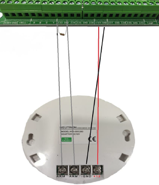
4. For the detector's power connection, use the "+12V" (positive 12V) and "-GND" (negative ground) connections on the panel.
88 – 1 = 15V normally, 5V at alarm time
88 – 0 = Normally 5V, at alarm time 15V
Supports SIA and ADEMCO Contact ID.
1. For panels owned by us, use the "ON" position.
2. Not used.
3. LED
Panels that belong to us (Old-New) should be in the "ON" position on 3 switches.

While dialing via the keypad connected to the alarm panel, you must put the number 1 in front of the password you entered to disable the alarm. In this case, the alarm will be disabled. However, in this particular case, a threat signal will be sent in addition to disabling the alarm.
This feature is part of your alarm system and is important for security. When you disable the alarm by prefixing the password with the number 1, the system also sends a threat signal to indicate an emergency or threat. This allows security personnel or the alarm monitoring center to be notified quickly and allow them to intervene if necessary.
After changing the user password used to control the alarm panel, a panel reboot is required to call and control the panel and apply the changes.
After changing the user password, the alarm panel may require a reboot to recognize this new password and work with the current settings. A reboot clears the panel's memory and makes it work in accordance with the new password.
Therefore, if you want to control the alarm panel by calling after changing the user password, you have to restart your panel.
- On average, a detector draws 0.5 amps of current. - A siren draws 1.5 amps on average.
- When the alarm panel is empty, it draws an average of 0.5 amps when only the keypad is connected.
These values are hourly average current draws and are provided for general reference.

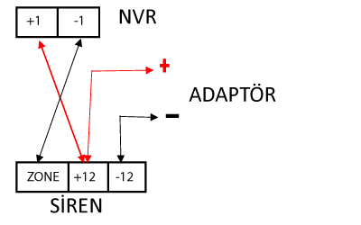
When using a 12v siren, the connection is as on the left.
- Width: 24 cm
- Height: 29 cm
- Depth: 8 cm
These dimensions represent the width, height and depth values of the NTA-GNA8540 panel.
- Height: 12 cm
- Width: 15 cm
- Depth: 1.8 cm
These dimensions represent the width, height and depth values of the KPC 10 keypad.
When you type the number 6464 on the keyboard and log in, you are logged in with the master password and you can change your password.
1. Press and hold the "Pattern" key on the keyboard for a few seconds.
2. "Record" will appear on the screen, then navigate to the route you want to record.
3. After completing the route, press the "Pattern" button again to finish the route.
4. Then if you press the "Run" button, it will start navigating the route you set.
By following these steps, you can save and run the pattern you set on the NT-002 keyboard.
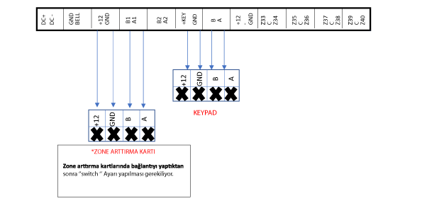
1. Zone increase card – (41-48) – 0 I 0 I
2. Zone increase card – (49-56) – I 0 0 I
3. Zone increase card – (57-64) – 0 0 0 I
4. Zone increment card – (65-72) – I I I 0
5. Zone increase card – (73-80) – 0 I I 0
(0) OFF
(I) ON
When connecting detectors, it is important to correctly connect the trigger leads and use resistors. You can make the correct connection by following the steps below:
1. First, connect one of the detector's trigger leads with a '10K' resistor to the "ZONE" port.
2. Connect the other trigger end to the "COM" port.
In this way, you have correctly connected the trigger ends of the detectors. In this way, the signals of the detectors are transmitted correctly and the system works properly.

4. Switch has no function. After performing this operation on the keypad, restart the Panel. When connecting to the panel via WEB, enter the keypad area from the region settings.
If the display disappears even though there is power on the keypad, you can solve the problem by resetting it to the default settings from the "WEB" (web) interface of the panel.
By pressing the combination 197804179#" on the keypad without entering the menu, it will allow you to return the alarm panel to its default factory settings.
*In case you forget the menu entry password, you can enter the menu by entering the numbers 840618.
Add 144 on top of the first three digits in the middle of the smart key.